The Task: Automating Coil Winding
Coil winding is the process by which copper coils are made — coils that are essential to electronics, since both inductors and motors rely on them to function. Machines that automate this process already exist, but many still require a significant degree of human interaction: mounting the spool, setting the wire, cutting it at the end, and fixing the finished coil in place.
This project set out to prototype a machine with a greater degree of automation, intended as a replacement for a current machine within a fictional company — and to determine whether investing in the new machine would actually benefit that company.
Process: Design and Improvement
The machine was developed using the stage-gate product development process. Initial research led to a set of generated concepts, from which specifications were defined — targeting as much automation as feasible, including an automatic loader and unloader. The design was split into three modules: a wire-cutting module, a loader/unloader module, and a winder/spindle module.
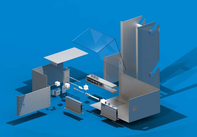
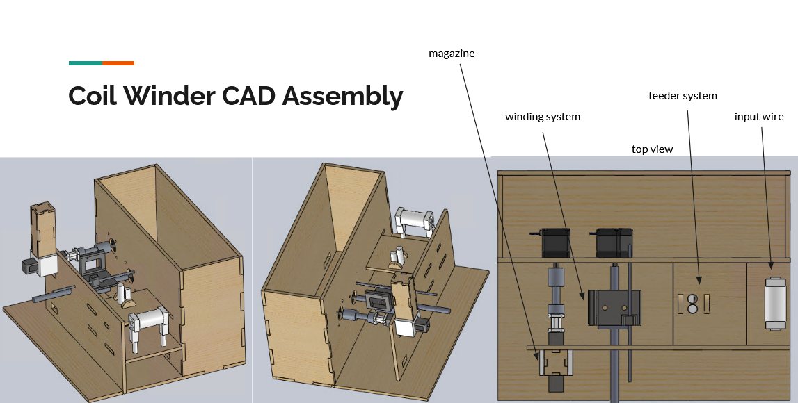
As more information became available through the process, the design was refined and finalised into the working prototype. The separate module models were combined and set within a single fixture — using CAD to let the modules be designed to interact correctly with each other, rather than relying on trial and error. The fixture itself was made from laser-cut MDF for ease of manufacture, mounted on a rectangular base of steel square tube, with a polycarbonate cover for safety.
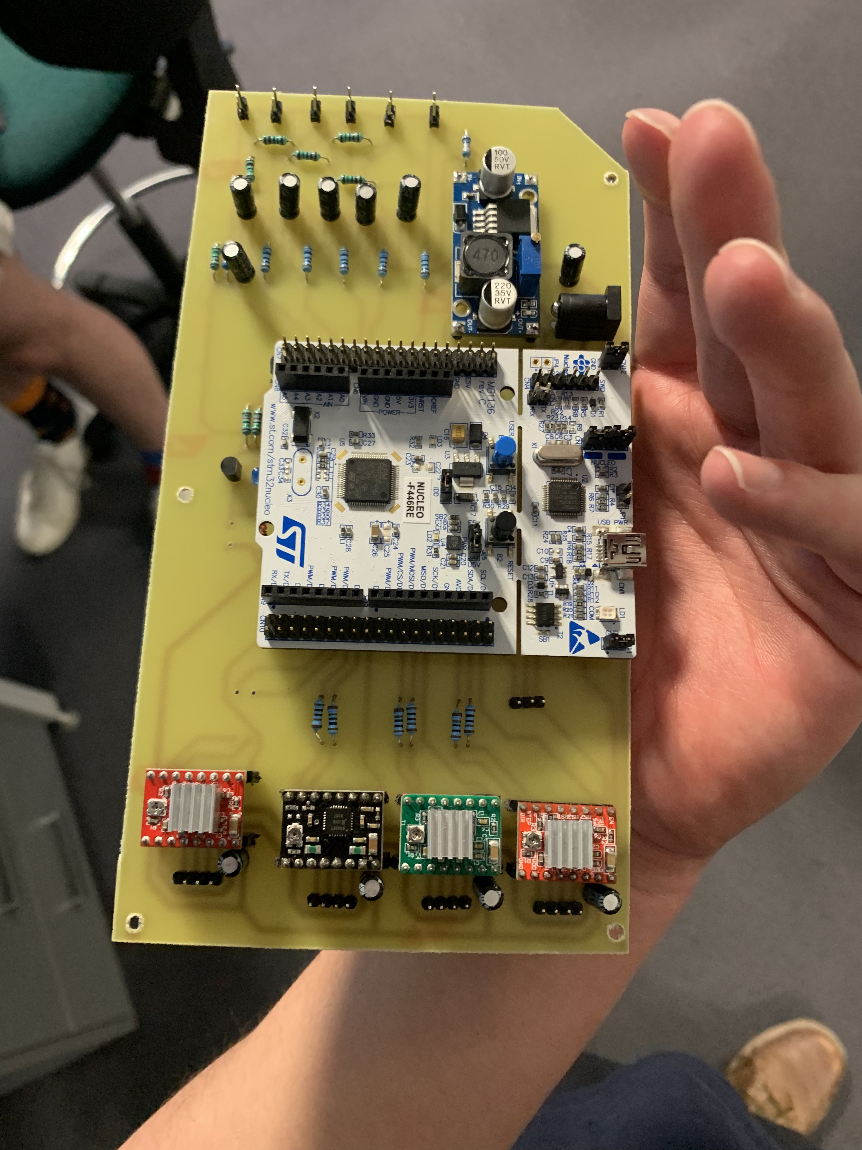
The control electronics were built around an STM32 Nucleo board, with the logic board and motor driver stages laid out and soldered onto a custom PCB to drive the winding, cutting, and loading modules.
Results & Conclusion
The group concluded that the machine was worth continuing development on: it was both technically and financially feasible, and offered better features than the fictional company's existing setup. The prototype itself wasn't a finished product — it would need further development to work through teething issues before it could be marketable.
The project was a strong demonstration of what a second-year Mechatronics Engineer should be capable of, and a key learning experience — sharpening both technical know-how and the ability to work effectively as part of a team on complex, difficult projects.